Today I want to share with you the history of the development of a device for controlling a multi-apartment intercom using the Zigbee protocol.
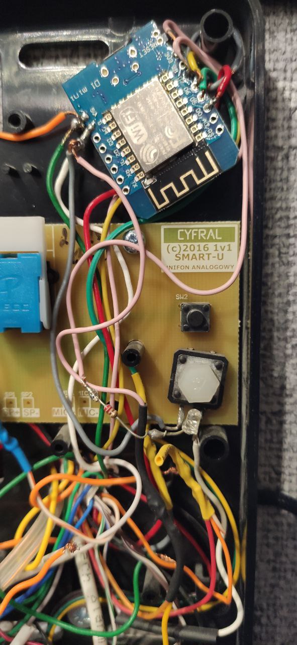
Once upon a time I had an automatic doorphone opener based on: ESP8266, a module for two relays (16A) and a transistor with a strapping.
All this was collected on a bunch of wires and snot made of hot melt glue and looked something like the second photo.
After organizing a Zigbee network at home, there was a desire to transfer as many devices as possible from to Zigbee in order to unload the Wi-Fi network (now there are 32 devices on Zigbee, and 20 devices on Wi-Fi).
Inspired by Jager devices and Anonymous firmware, it was decided to make an intercom opener on Zigbee. Surfing the vastness of the network, I came across a project of a similar doorphone opener, authored by Alexander Vaidurov.
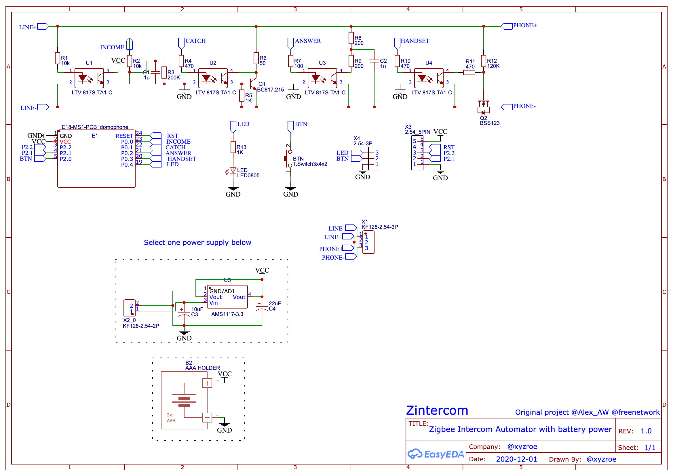
I really liked the idea of using optocouplers instead of relays and the option of battery power supply for the device. With his consent, it was decided to use the part of the circuit responsible for working with the intercom line, but to make the control on the CC2530 chip.
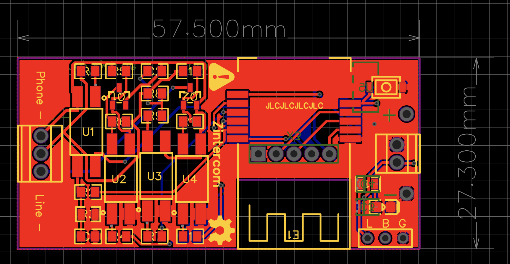
The following scheme turned out:
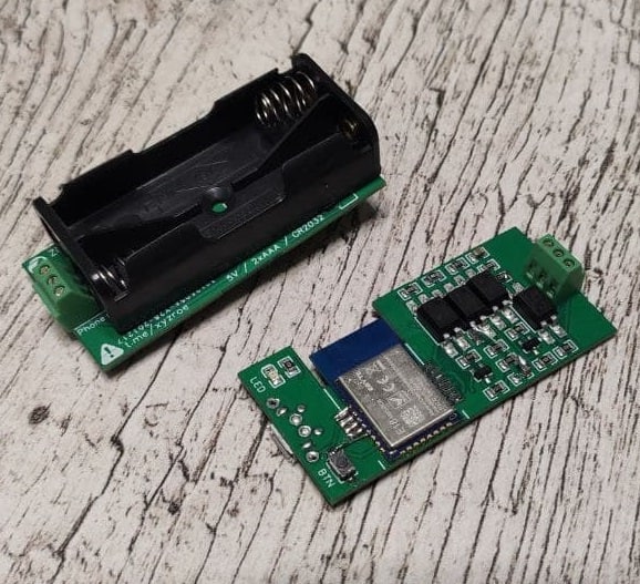
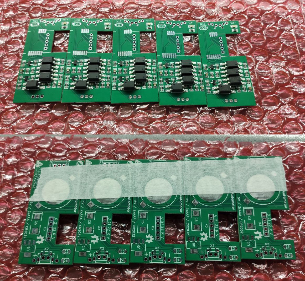
Then I spread the board and ordered it from the Chinese.
I wanted to place an order before the holidays, and hastened. As a result, there were a couple of small mistakes that had to be corrected with jumpers.
(Don’t rush! Don’t repeat my mistakes)
There was also a discount coupon - decided to try a surface mount order. It turned out about $ 18. (This is more of a curiosity than a real need - the soldering is very simple)

While the boards were being manufactured and driving, the firmware for the device was written and a converter for zigbee2mqtt was made.
Dashboard zigbee2mqtt
Exposes zigbee2mqttIn total, what opportunities do we have:
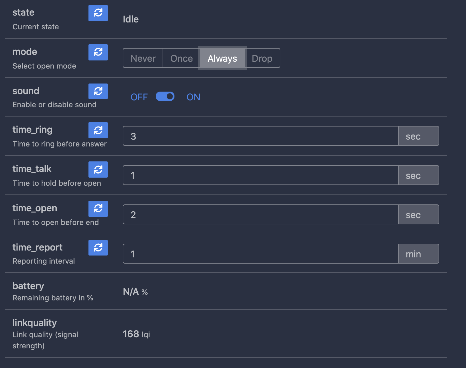
Receive notification when the intercom rings (OnOff direct binding is also supported)
Do not interfere with the intercom (Never mode)
Automatically open to everyone (Always mode)
Open the door once during a call, or at the first call after switching on (Once mode)
Dump all incoming (Drop mode)
Mute the sound on the intercom handset (or use it without a handset at all)
Call time, waiting time, opening time and report sending interval are configured through exposes.
For debugging, a second-hand semi-working set of the digital outdoor panel and the Vizit handset was purchased for symbolic money (about $ 15)
Video demonstrating different operating modes (1.5X)
In the course of debugging and testing, there were some changes:
Some resistors and capacitors have been changed Fixed a couple of bugs in the PCB layout Removed space for 2032 (change too often) Removed micro USB connector (too inconvenient soldering)
Final renders
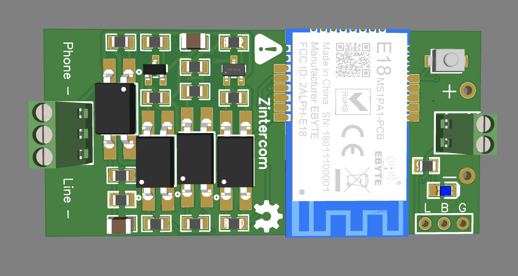
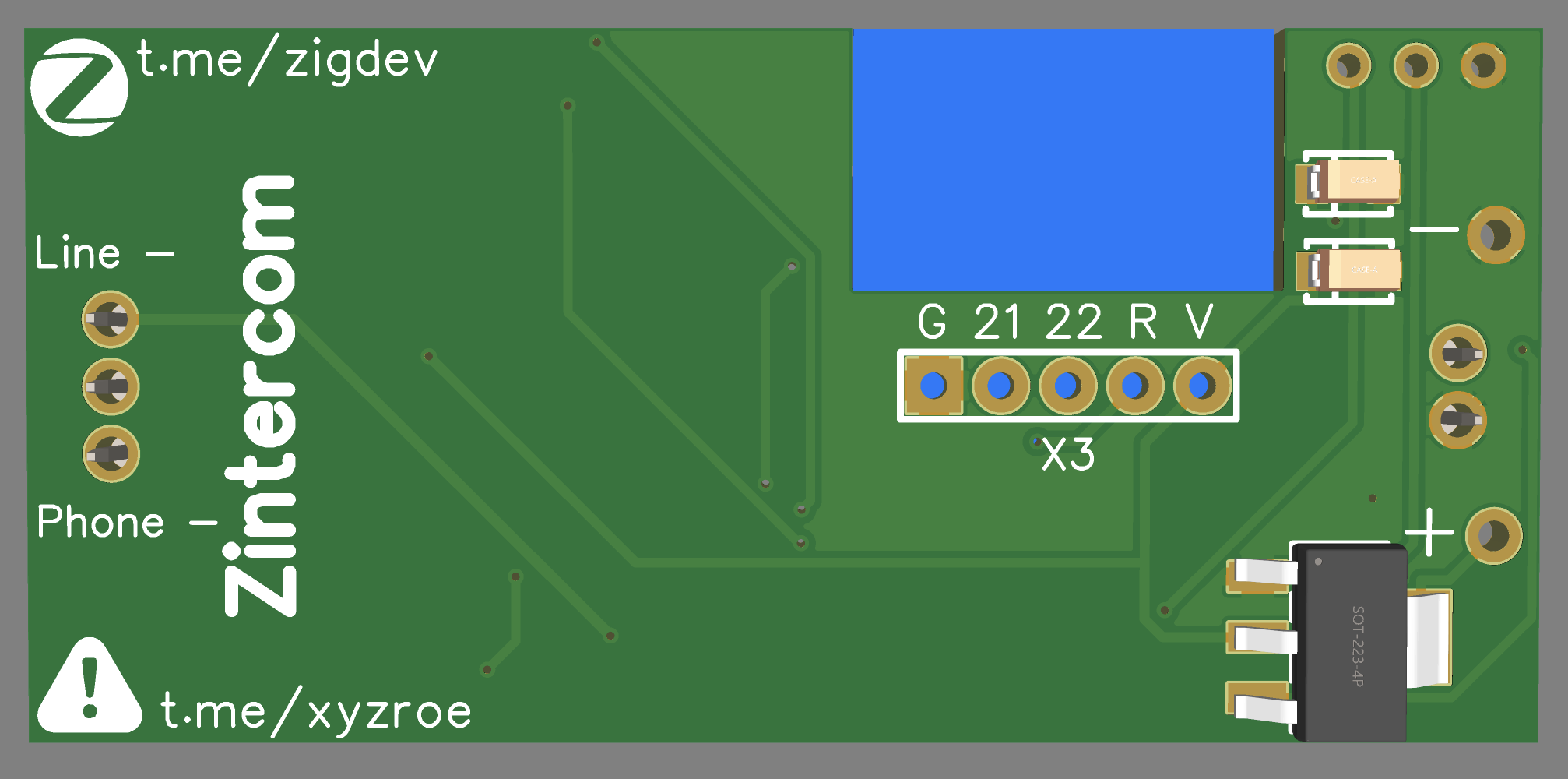
Differences between constant and battery power supply:
With constant:
Interval for sending reports - 1 minute Battery status is not sent Router or end device mode
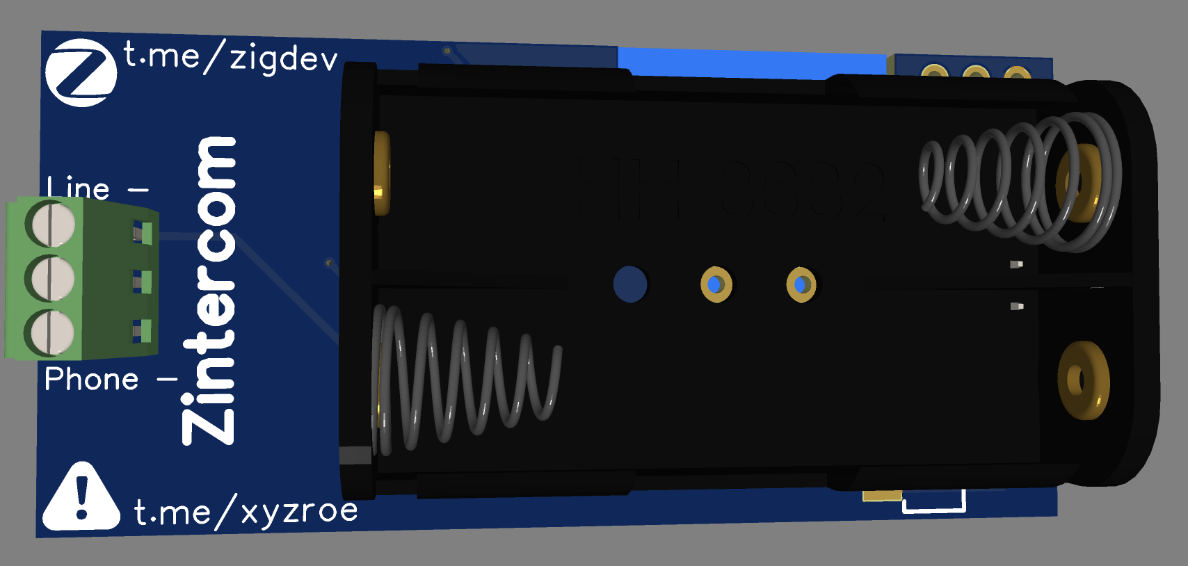
With battery (E18-MS1-PCB only):
Interval for sending reports - 30 minutes Battery status is sent after every event (call / button press) End device mode only Since the device is in sleep mode, it cannot receive commands, but it is possible to change the mode with a button or Zigbee command at the time of a call.
Do not turn off the sound, because it keeps the U2 on all the time, which drains the battery much faster. If any commands are in the coordinator’s queue, they will be executed when the device wakes up - after pressing a button or after receiving an incoming one.
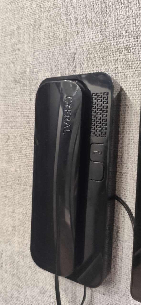
After all the tests, I installed the board in the intercom tube case:

Firmware, diagrams, Gerbers (also v2) are open and available on the project’s